LOGIC GATES
In digital electronics, the decision making capability of the gate circuit is called logic, and a type of logic circuit that performs a specific logical operation e.g AND or OR etc is called a gate. So, the logic gates are the type of electronic circuits that makes logical decisions, and their output depends on the preset rules. The logic gates can have multiple inputs but always has a single output. A gate is just like a switch which can be ON or OFF. The ON state represents logic 1, while the OFF state represents logic 0. A gate can not only add, subtract, count, etc but can also store the information.
The most common types of the gates;
In Boolean Algebra, there are three basic operations,  which are analogous to disjunction, conjunction, and negation in propositional logic. Each of these operations has a corresponding logic gate. Apart from these there are a few other logic gates as well.
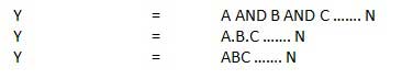
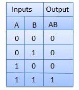
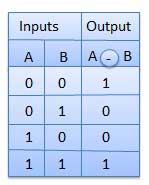
- AND gate (.)– The AND gate gives an output of 1 if both the two inputs are 1, it gives 0 otherwise.
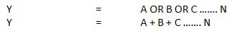
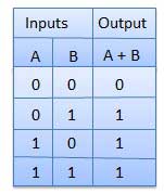
- OR gate(+) – The OR gate gives an output of 1 if either of the two inputs are 1, it gives 0 otherwise.
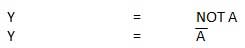
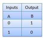
- NOT gate(‘) – The NOT gate gives an output of 1 input is 0 and vice-versa.
- XOR gate(
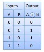
 ) – The XOR gate gives an output of 1 if either both inputs are different, it gives 0 if they are same.
- NAND gate(
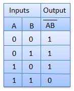
 )- The NAND gate (negated AND) gives an output of 0 if both inputs are 1, it gives 1 otherwise.
 - NOR gate(
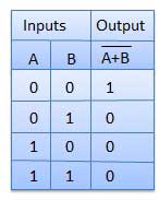
 )- The NOR gate (negated OR) gives an output of 1 if both inputs are 0, it gives 0 otherwise.
 - XNOR gate(
 )- The XNOR gate (negated XOR) gives an output of 1 both inputs are same and 0 if both are different. LOGIC GATE SYMBOLS
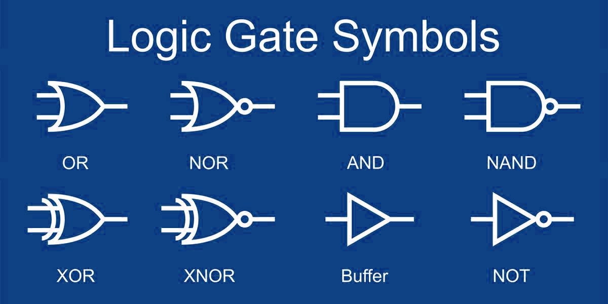
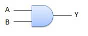
A circuit which performs an AND operation is shown in figure. It has n input (n >= 2) and one output.
Logic diagram;
Truth Table;
2.OR GATE;
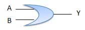
A circuit which performs an OR operation is shown in figure. It has n input (n >= 2) and one output.
LOGIC DIAGRAM;
TRUTH TABLE;
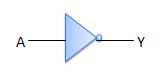
3.NOT GATE;
NOT gate is also known as Inverter. It has one input A and one output Y.
LOGIC DIAGRAM;
TRUTH TABLE;
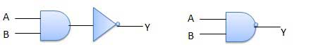
A NOT-AND operation is known as NAND operation. It has n input (n >= 2) and one output.
LOGIC DIAGRAM;
TRUTH TABLE;
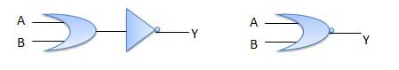
A NOT-OR operation is known as NOR operation. It has n input (n >= 2) and one output.
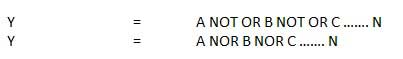
LOGIC DIAGRAM;
TRUTH TABLE;
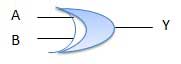
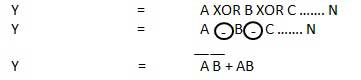
XOR or Ex-OR gate is a special type of gate. It can be used in the half adder, full adder and subtractor. The exclusive-OR gate is abbreviated as EX-OR gate or sometime as X-OR gate. It has n input (n >= 2) and one output.
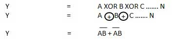
LOGIC GATE;
TRUTH TABLE;
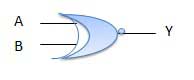
XNOR gate is a special type of gate. It can be used in the half adder, full adder and subtractor. The exclusive-NOR gate is abbreviated as EX-NOR gate or sometime as X-NOR gate. It has n input (n >= 2) and one output.
LOGIC DIAGRAM;
TRUTH TABLE;
Comments
Post a Comment